USE OF ASSEMBLY MAXON MOTOR 399505 WITH SET МСВ-04
USE of ASSEMBLY Maxon Motor 399505 WITH SET МСВ-04
In frame of improving procedures of training sets our company «NPF Mechatronica-Pro» has received for testing the dc drive components manufactured by Maxon Motors. The electric drive consists of:
- DC motor - RE-max 24 Part Number(PN) 222053

- Planetary-gear reducer - GP 22 C PN 143979
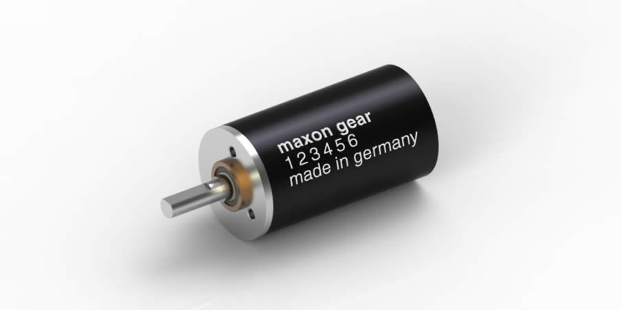
- Quadrature encoder – MR type ML PN 201940
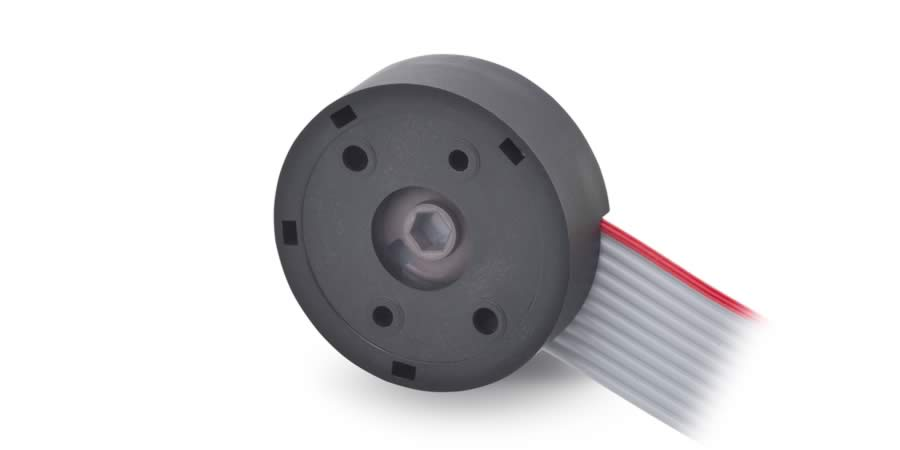
Assembly of these components is aggregate 399505, which is ready to connection to set МСВ-04, whose parameters are shown in table 1.
Table 1
|
Parameter |
Value |
|
RE-max 24 PN 222053 |
|
|
Rated voltage |
24 V |
|
No-load speed |
9250 rpm |
|
No-load current |
27,3 mA |
|
Rated Speed |
7590 rpm |
|
Rated current |
0,487 A |
|
Rated torque |
11,3 mNm |
|
Armature resistance Ra |
9,02 Ohm |
|
Armature inductance La |
0,406 mH |
|
Moment of inertia |
4,27 g*sm2 |
|
GP 22 C PN 143979 |
|
|
Gear ratio of reducer |
29:1 |
|
Number of passes of gearing |
2 |
|
Moment of inertia |
0,4 g*sm2 |
|
MR type ML PN 201940 |
|
|
Counts per revolution |
512 |
|
Number of channels |
3 |
|
Supply voltage |
5 V |
|
Output current per channel |
0..5mA |
|
Moment of inertia |
0,09 g*sm2 |
Standard set МСВ-04 has specification listed in table 2, which show that available power and control cards of the set can be used to control the assembly 399505 manufactured by Maxon Motors.
Table 2
|
Parameter |
Value |
|
Power Card |
|
|
Rated supply voltage |
24 V |
|
Maximum current |
13 A |
|
Output voltage |
0..24 V |
|
Control Card |
|
|
Supply voltage of encoder |
5 V |
|
Number of channels of encoder |
6 |
Since the assembly is compatible with the set, let’s connect them. To do so, connect the output ribbon cable of the assembly according to connection circuit (Fig. 1) to the set into corresponding connector, as it is shown in fig.
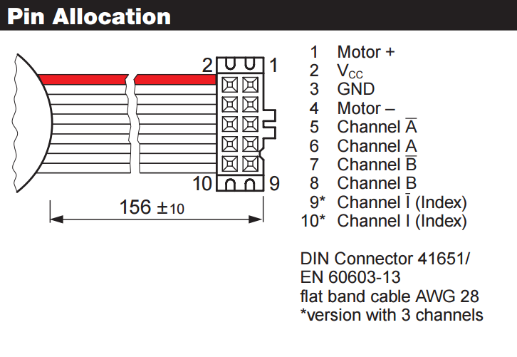
Fig. 1 Circuit of the assembly connection
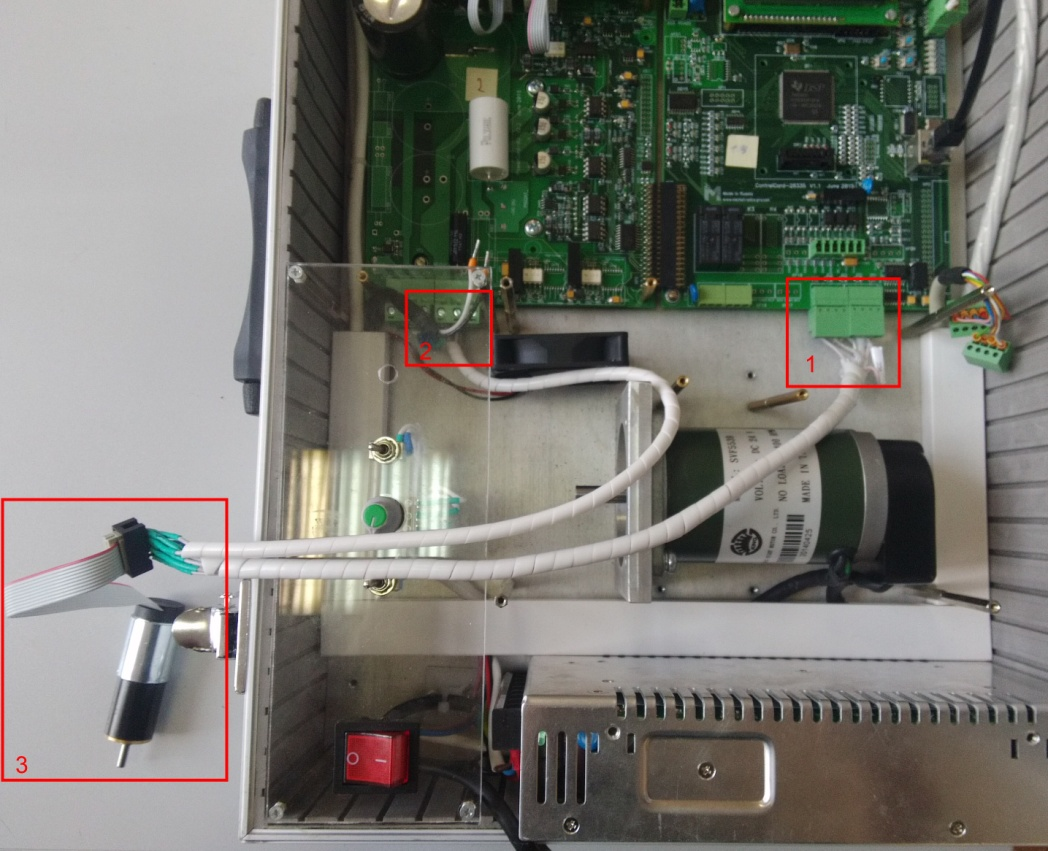
Fig. 2 Connection to the set , 1 – Encoder connectors, 2 – Power connectors, 3 – Tested assembly
After connection of the assembly to the set let’s do several starts in direct an inverse directions to check the correctness of the connection.
To develop the control system of the motor let’s create a project under MexBIOS Development studio environment for embedded system software development.

Fig. 3 Basic project under MexBIOS Development Studio environment
Parameters of blocks and their functions are listed in table 3.
Table 3
|
Block type |
Parameters |
Function |
|
EVENT |
Source: 2: Hardware Vector: 26:TINT0 Period: 0.0002 Emulation mode: Continuous |
Interrupt setting that calls the main program with frequency of 5kHz |
|
FORMULA |
Name: Driver |
Formula that contains sensor blocks |
|
Name: PWM |
Formula that contains blocks, which form reference of the duty factor of the inverter switches |
|
|
TRACKBAR |
Minimum: -0.9 Maximum: 0.9 Step: 0.1 Precision: 2 Format: 31: float Value: 0.0 |
Reference set block for duty factor of switches |
|
BUTTON |
Group: 1 Value «Released»: 1 Value «Pushed»: 0 Format: 0: Integer Value: 1 |
Button of enabling PWM with fixation |
|
GPIO |
Type: 1: Output Pin: 31: GPIO31 |
Enable- PWM pin |
|
fINV |
Input Inversion |
|
|
PWM6 |
Id: EPWM1-3/GPIO0-5 Frequency: 5000 |
Control block of the inverter switches |
After setting the corresponding blocks let’s connect to the set and load the project into RAM. Pushing BUTTON after begin of refreshing causes lighting-on green LED PWM in control card, however the shaft of the assembly does not move, since the reference for duty factor in block TRACKBAR is equal to zero. By changing the scrolling in the box, make sure that the motor speed is changed both in value and in direction. Thereafter let’s tune the controllers.
In general the structure of the subordinate control system is shown in block diagram in fig. 4

Fig. 4 Block diagram of control system
This diagram takes into consideration parameters of the assembly motor only, since its mechanical parameters are by an order of magnitude greater than the parameters of encoder and reduced, therefore they can be neglected.
As you can see from the structure for the operation of the control loops the corresponding feedbacks are needed, which come from outputs of sensors. Dealing the sensor outputs is function of formula Driver, whose structure is shown in Fig. 5, and the parameters of the blocks are listed in table 4.

Fig. 5 Structure of block Driver
Table 4
|
Type of block |
Parameters |
Function |
|
ADC |
Frequency: 7:10714 Chan1: 8:ADCINB0 |
Analog-to-digital conversion, which measures current in U phase |
|
QEP |
PosMax: 2048 |
Block of the encoder counts calculation, where PosMax is number of the pulse edges per 1 revolution (4*number of slots per revolution) |
|
fOFFSET |
GainA: 0.000415 |
Block of automatic determination and implementation of required shift for ADC during specified time. How to determine the scaling factor is described below |
|
fSPEED_CALC |
SampleTime: 0.0002 BaseSpeed: 9250 |
The block calculates the shaft rotation speed based on data from QEP and rated speed setting. The result is output in p.u. |
|
fGAIN |
Gain: 9250 |
Conversion from p.u. into rpm |
|
TP_OUT |
tag: Current |
Transfer of the current value into block PWM |
|
tag: Speed |
Transfer of the speed value in rpm |
|
|
tag: Wr |
Transfer of the shaft rotation speed in p.u into block PWM |
. The scaling factor can be determined in the following way:
- Insert into armature circuit a multimeter t measure the armature current
- Start the motor and register the mean value of the current in steady-state
- Determine the scaling factor from reading of label LCurrent (block Label) by dividing the real current by reading from AD module and by entering the resulted value as parameter GainA of block fOffset.
Tuning of the subordination control system is carried out according to known methods of loop tuning. First let’s tune the inner current loop to the modular optimum:

Let’s determine parameters of the current loop controller:

To check quality of the loop tuning we need to assemble a circuit, which provides instantaneous reversing. To achieve it let’s add to the circuit that was assembled earlier in formula PWM the blocks that are shown in table 5 and in Fig. 6.

Fig. 6 Structure of block PWM for tuning the current loop
Table 5
|
Type of block |
Parameters |
Function |
|
TRACKBAR |
Minimum: 0 Maximum: 0.5 Step: 0.1 Precision: 2 Format: 31: float Value: 0.0 |
Current Reference |
|
fMPY |
Current Sign Reference |
|
|
Button1 |
Group: 0 Value «Released»: 1 Value «Pushed»: -1 Format: 31: float Value: 1 |
Reversing Button |
|
fAP1_Filter |
SampleTime: 0.0002 Tf: 2 |
First-order filter for decreasing the oscillation in the current channel |
|
fPID |
Kp: 1.616 Ki: 0.1213 Kc: 0.1213 Kd: 0 Min: -0.9 Max: 0.9 |
PID-controller of the current loop. |
|
TP_IN |
Тег 1:Current |
Input signal from ADC block |
Start of this circuit allows us visually to estimate the speed of the drive response to the sign change of the current reference.

Fig. 7 Current loop operation in reversing mode of the current reference
Let’s insert the calculated parameters in block of PID-controller and carry out the same study of the response speed. Reversing after parameter inserting should be fulfilled with the same response speed, as in previous experiment.
After successful tuning if the current loop let’s tune the speed loop:

It should be noted that tuning of motors with very fast response because of small moment of inertia, the formulas for determining tuning parameters of symmetrical optimum slightly differ from the standard ones.
Let’s add the circuit from Fig. 6 by second loop as it is shown in Fig. 8

Fig. 8 Structure of block PWM при for tuning the speed loop
Table 6
|
Type of block |
Parameters |
Function |
|
fPID1 |
Kp: 0,399 Ki: 0.002363 Kc: 0.002363 Kd: 0 Min: -0.4 Max: 0.4 |
PID-controller of the speed loop. |
|
TP_IN |
Tag 1:Wr |
Input signal from block Speed_Calc |

Fig. 9 Results of the speed loop operation
Let’s implement the outer loop of the system – position loop to get position servo-drive – an electric drive that moves the output shaft to required angle without compliance to a motion curve.
A feature of such systems is supposed to be slightly oscillatory character of the speed in steady-state operation due to some neglecting in calculations. One of simple methods to reduce the influence of these phenomena under MexBIOS environment is to decrease the calculation frequency of individual component or of the group of components, this method allows in our case to call the position controller calculation with smaller frequency, which causes the oscillation decrease without change in static error. However you should not set very low frequency of the block calling, optimum value would be scaling frequency ratio, whose value is in range 5..100 as a function of the motor response speed.
The algorithm can be realized in the following way:
In the first place you need to make alterations in the main body of the program as it is shown in Fig. 10 and table 7

Fig. 10 Main program for the drive operation with three control loops
Table 7
|
Type of block |
Parameters |
Function |
|
Var |
Имя Name: VAR Format: 0:Integer |
Variable-Flag for indication that the calculation frequency has been decreased |
|
If |
Condition: 1: Equal Value 1: 1:VAR Value 2: Constant = 1 Format: 0:Integer |
Block of condition: either the calculation frequency has been decreased or not |
|
Formula |
Имя Name: Pos_Loop |
Position loop |
Thereafter let’s go into formula Driver and add the teleport labels and blocks of frequency scaling, as it is shown in Fig. 11

Fig. 11 Formula Driver for position loop
Table 8
|
Type of block |
Parameters |
Function |
|
IN |
Format: 0: Integer Value: 100 |
Reference of the frequency scaling factor kSCALING |
|
FREQ_DIVIDER |
Block of calculation frequency divider |
|
|
Out |
Format: 0: Integer Variable: 1:VAR |
Output flag of the scaling frequency event |
|
TP_OUT |
Tag: Pos_Fdb |
Transfer of the current value to block Pos_loop |
Next let’s go into formula Pos_Loop that contains the position controller block. Fig. 12.

Fig. 12 Position loop
Таблица 9
|
Type of block |
Parameters |
Function |
|
fPid |
Kp: 0.000027 Ki: 0 Kc: 0 Kd: 0 Min: -1 Max: 1 |
Position PID-controller |
|
IQTOF, IQTOF1 |
Format: 0:Integer |
Block of the data format change |
|
TP_IN |
Tag: Pos_Ref |
Angular displacement reference |
|
Tag: Pos_Fdb |
Current value of angular displacement |
|
|
TP_OUT |
Tag: Wr_ref |
Reference for speed controller |
The tuning parameters (factors) of the position controller can be calculated in terms of formulae:
Next let’s go into block PWM to change it according to Fig. 13

Fig. 13 Block PWM for position loop
Table 10
|
Type of block |
Parameters |
Function |
|
IN |
Format: 31: Float |
Block of angular displacement reference, the reference can be changed in progress via Monitor of the variables |
|
TP_OUT |
Tag: Current |
Transfer of value of current into block PWM |
|
TP_IN |
Tag: Wr_ref |
Speed reference |
Finally we developed a control system of the servo drive, where the reference of angular displacement in form of number of counts of encoder is set in block In. Results of the position drive operation are shown in Fig. 14, Fig. 15.

Fig. 14 Motor shaft speed transient for positioning to required rotation angle

Fig. 15 Rotor position transient